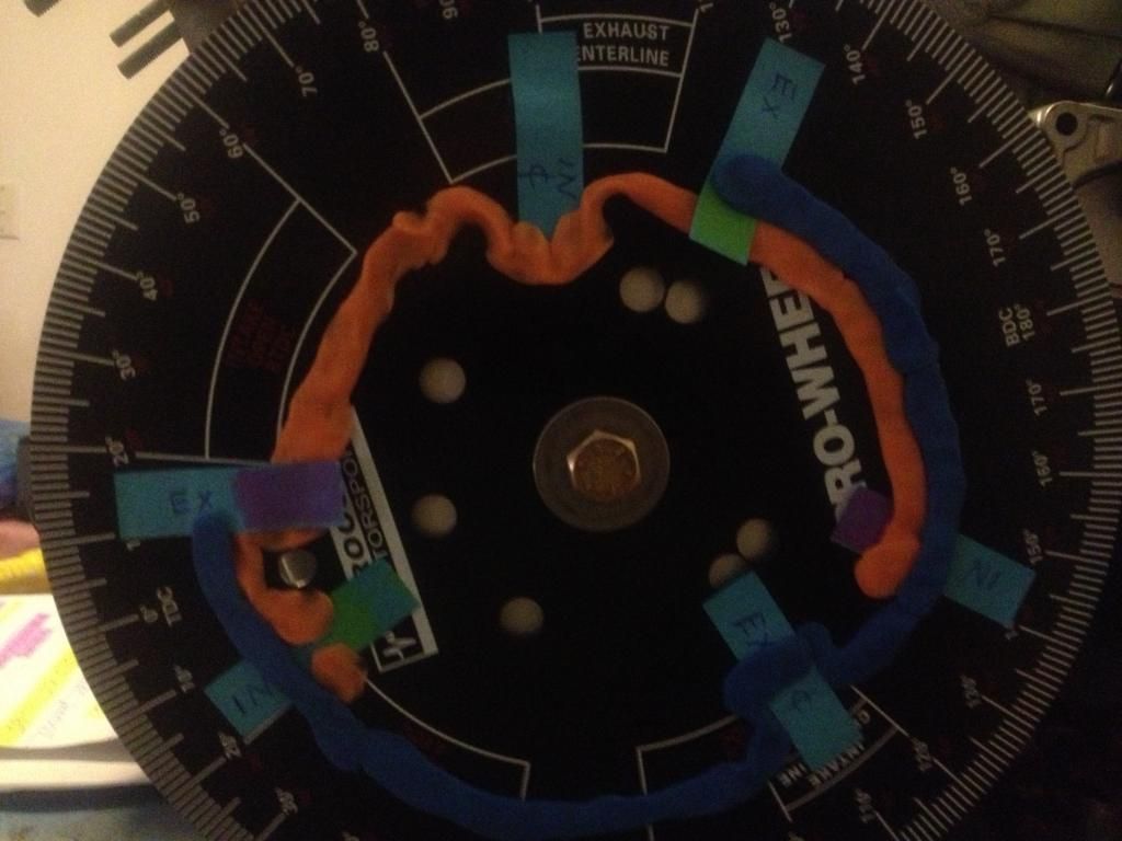
Now I can get a visual perception on how the inlet and exhaust valve work in relation with each other..
Just follow the orange brick road

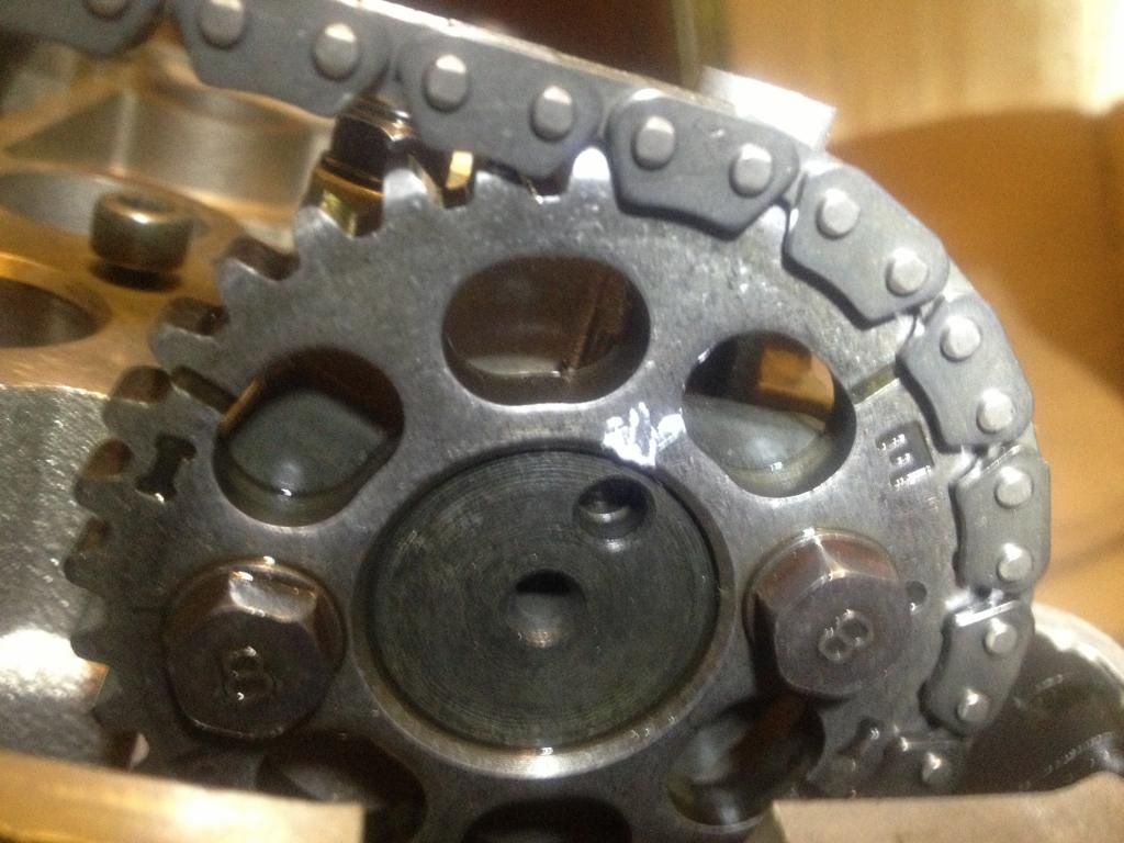
What I can see now too is where the factory timing marks are positioned is right where both valves are closed on compression stroke.
This is why the inlet and exhaust cams on No.1 are set up 180* and centre of the base circles facing each other.
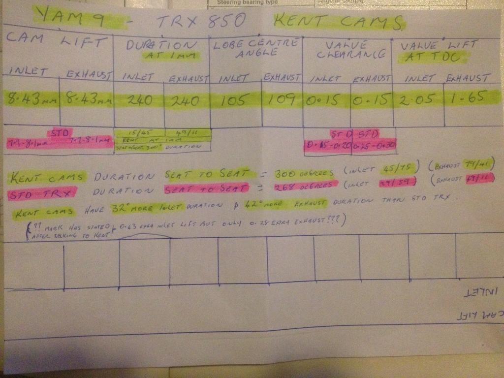
So now I plan to remove the head from the motor and mount the head solidly on the bench so I can use a dial indicator and place my own timing mark on the cam to line up with the cam journal cap. I'll mark this at 1mm lift...
I plan to use the dial indicator on the valve head itself from inside the chamber and once i get 1mm lift, place a mark on the cam itself. ( These will be a number of degrees from the Yamaha punch mark)
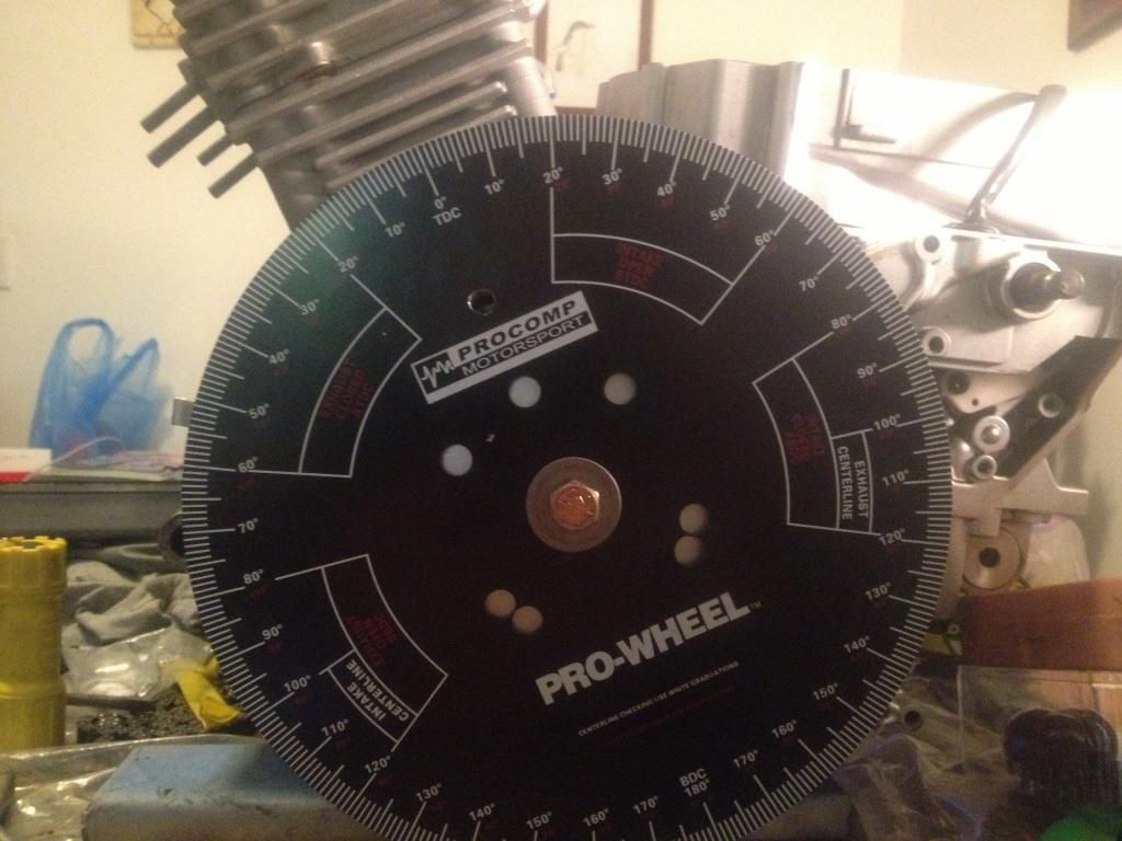
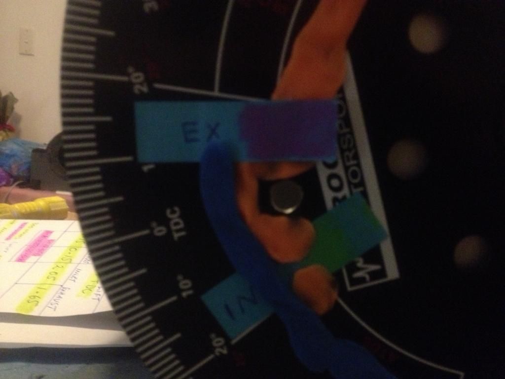
So i now have a TDC mark to work from. Set the cams up as per factory spec using the factory punch marks and when I rotate the crank to my Kent spec lobe centre angles of 105 inlet and 109 exhaust, I should be able to rotate the cam within the slotted cam gear to meet my new 1mm duration marks.
When back at TDC on compression stroke, the factory punch marks may end up a couple of degrees from their original position
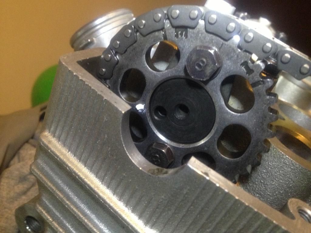
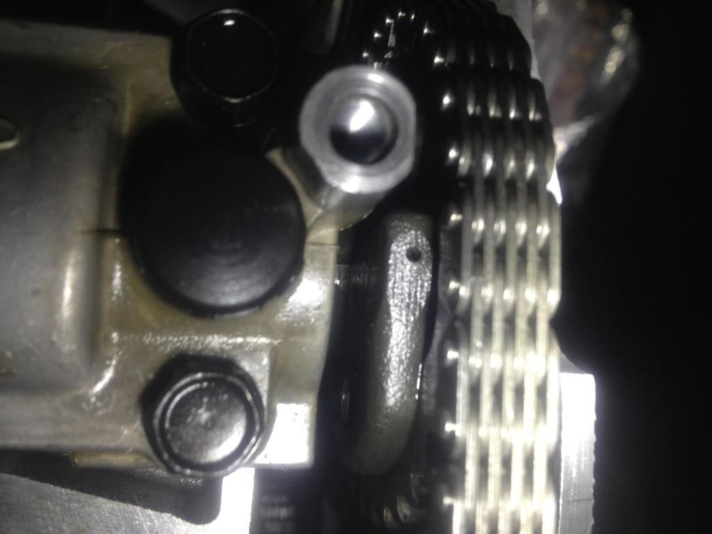
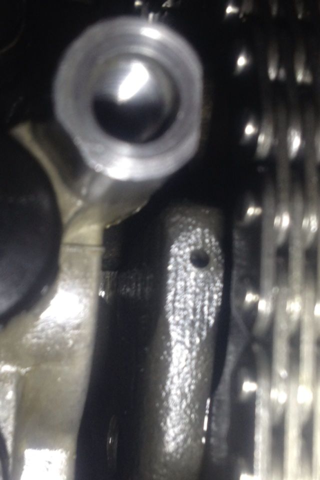
To give myself a ballpark mark, I checked where the lobe centre marks would be and,,,,and guess what, they are already indicated by the large hole on the end of the cam itself where the cam sprocket bolts on. But I still need to mark this point on top of the cam with the dial indicator method.