Nope, Tornados from Germanycobbadiggabuddyblooo wrote:Pretty sure Killer has the MEGACYCLE cams on his bike.
What did you do today? Cobba's rebuild
Moderators: trixynut, Mincehead, dicky, phuk72, Jak, Kevtrx849
-
Killerwhale

- Site Sponsor
- Posts: 3797
- Joined: Tue Aug 22, 2006 8:41 am
- Location: GBG/Sweden
- Contact:
Re: What did you do today? Cobba's rebuild
-
cobbadiggabuddyblooo
- Site Sponsor
- Posts: 6809
- Joined: Thu Aug 28, 2008 9:19 am
- Location: Brisbane,Australia
Re: What did you do today? Cobba's rebuild
Tornado's ....Are they the one's Hubi sells???
Talking to Ulf from another forum, he put me onto him as the cams they put together lay inbetween the V2 and MEGACYCLE.
Ulf feels I find 110hp with the V2's and gave some good tips on dialing.
He also passed on the info on the std , V2 and mega cams.
Do you have any specs on the Tornado's Mathias??
(that's why the 4 or 5 line gap on the specs between the V2 - megacycle cams )
)
Talking to Ulf from another forum, he put me onto him as the cams they put together lay inbetween the V2 and MEGACYCLE.
Ulf feels I find 110hp with the V2's and gave some good tips on dialing.
He also passed on the info on the std , V2 and mega cams.
Do you have any specs on the Tornado's Mathias??
(that's why the 4 or 5 line gap on the specs between the V2 - megacycle cams
laughter is the best medicine
-
cobbadiggabuddyblooo
- Site Sponsor
- Posts: 6809
- Joined: Thu Aug 28, 2008 9:19 am
- Location: Brisbane,Australia
Re: What did you do today? Cobba's rebuild
Been spending a little time on the FCR's to study exactly how the curcuits interact.
plenty of info out there on what the curcuits are but no real pathway information so I went off on another learning curve.
So here is my basic understanding on the workings of the FCR carby for a TRX 850.
OK the purpose of the carburettor is to mix fuel and air at a certain ratio and due to different loads like idling, accelerating , cruising etc, the carby has different curcuits to deal with these. The fuel is subdivided or atomised so it can be mixed with air and this all occurs within the curcuits internally inside the carburettor before being introduced into a stream of moving air in the manifold.
The air/fuel mix is then vapourized assisted by heat and enters the cylinder.
A lower air pressure from atmospheric is created with the piston drawing down on the intake stroke and when the intake valve opens, the cylinder draws air through the carby.
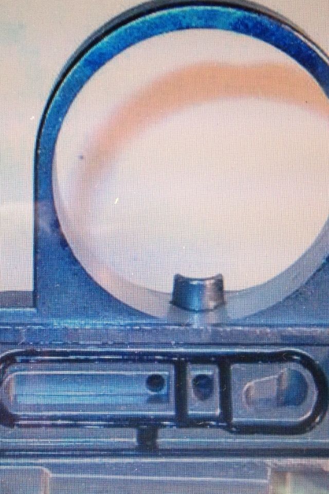
Here you can see the MAIN AIR jet and air screw. The main air jet is the source of all the air within the carburettor curcuits.
So your idle curcuit, pilot curcuit and main curcuit all draw air from here to do their atomisation task.
This MAIN AIR jet draws air all the way into the centre of the carby where your NEEDLE JET (emulsion tube) is screwed inplace.
The air from the main air jet circulates around the outside of the NEEDLE JET (emulsion tube).
When the needle jet is screwed inplace into the carb body and this is not a tight snug fit but a small gap exists around the outside of the Needle jet(tube) and the carb body for this very purpose. (but the outside top is sealed of cause, the inside is open for the needle to work it's magic via the 4 large hole near the bottom of the needle jet( e tube)
) The MAIN air feed enters up near the top outside of the NEEDLE JET into the void.
Now all curcuits can draw their air from around the NEEDLE JET (emulsion tube) but do so above where the MAIN FUEL jet also enters this void.

This drawing shows where your main fuel is drawn from the bowl through the main jet and you could imagine there are 3 small holes in the void around the needle jet above where the main fuel jet enters with the MAIN AIR being the top hole. The other 2 holes being the air feed for the idle and pilot curcuits.
The main air feed in is on top as the other curcuits have their own fuel feeds to draw out (fuel screw and pilot fuel jet).
Not the best drawing as it should show the fuel in red being drawn into the void, then the atomised air/fuel down to the bottom and up in through the centre of the JET NEEDLE
Remember the negitive pressure created on the intake stroke draws air in through the carby and when drawn past the JET NEEDLE and the opening of the NEEDLE JET (emulsion tube), this sucks the atomised fuel up on the main curcuit. Now you realise why the air feed from the other curcuits need to be above the fuel feed so they are not being comprimised by the main fuel feed.
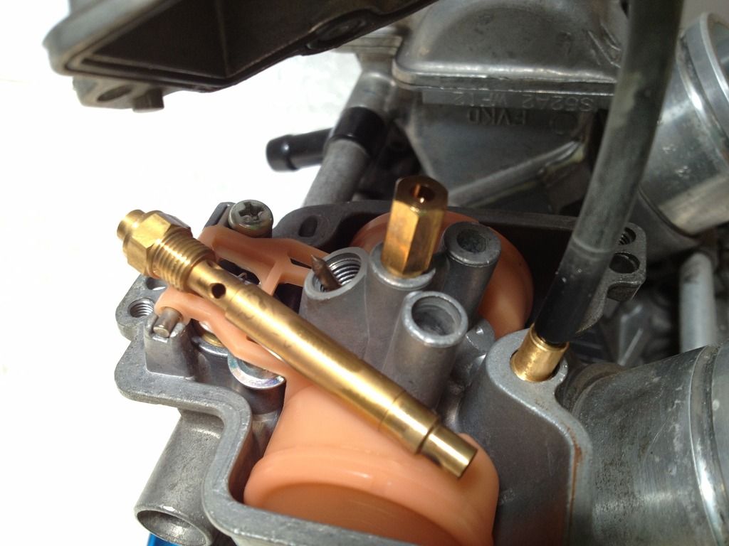
The AIR SCREW works in tandem with the PILOT JET for adjustment of just off idle and small throttle openings 10%.
Air that is drawn from around the needle jet(tube) through either the middle or bottom air bleeds, as starts it's path in the pilot curcuit, it goes via the air screw and can be adjusted to gain an optimum atomised mixture with the fuel then this atomised fuel enters the manifold.
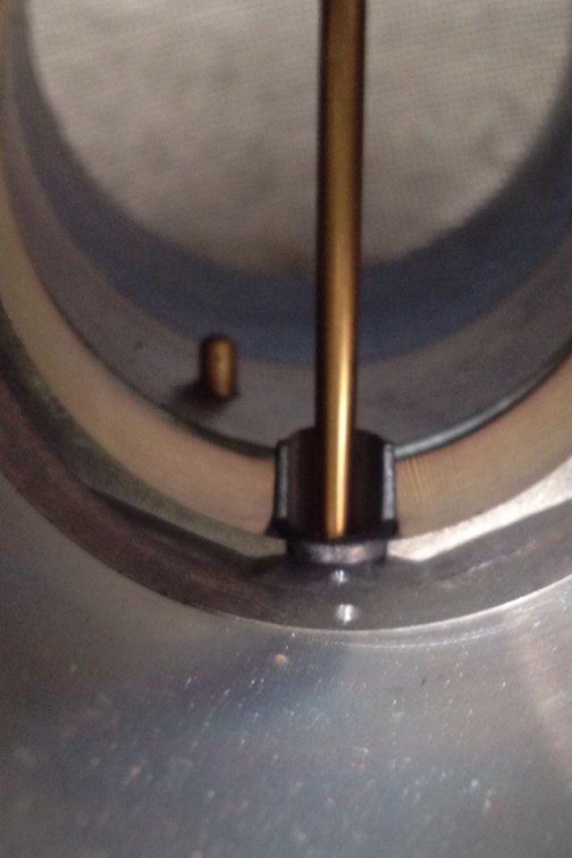
This pictures shows where the main air feed path heads to the void around the needle jet and the other is the air feed from the void to pass via the air screw.
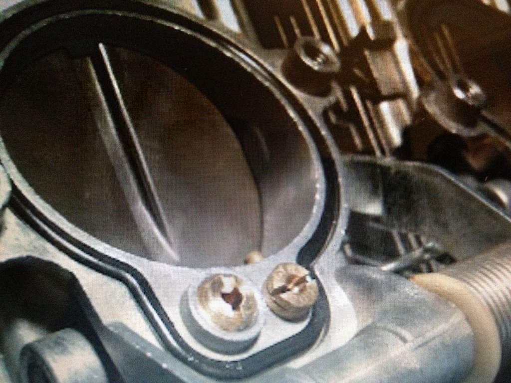
The next photo shows where the idle curcuit and the pilot curcuit atomised fuel is drawn into the intake manifold via the 2 tiny holes infront of the NEEDLE JET opening. Twist the throttle and the JET NEEDLE is lfted out of the NEEDLE JET, this opens the door for more atomised fuel to enter via the MAIN curcuit. And the accelerator jet in the background serves the purpose of sulyi g a shot of fuel when the throttle is opened quickly. The reason being that the Carby relies on the vaccum to draw atomised fuel up and until the motor can supply this messes art vaccum the ACC pump shot compensates through this period.
plenty of info out there on what the curcuits are but no real pathway information so I went off on another learning curve.
So here is my basic understanding on the workings of the FCR carby for a TRX 850.
OK the purpose of the carburettor is to mix fuel and air at a certain ratio and due to different loads like idling, accelerating , cruising etc, the carby has different curcuits to deal with these. The fuel is subdivided or atomised so it can be mixed with air and this all occurs within the curcuits internally inside the carburettor before being introduced into a stream of moving air in the manifold.
The air/fuel mix is then vapourized assisted by heat and enters the cylinder.
A lower air pressure from atmospheric is created with the piston drawing down on the intake stroke and when the intake valve opens, the cylinder draws air through the carby.
Here you can see the MAIN AIR jet and air screw. The main air jet is the source of all the air within the carburettor curcuits.
So your idle curcuit, pilot curcuit and main curcuit all draw air from here to do their atomisation task.
This MAIN AIR jet draws air all the way into the centre of the carby where your NEEDLE JET (emulsion tube) is screwed inplace.
The air from the main air jet circulates around the outside of the NEEDLE JET (emulsion tube).
When the needle jet is screwed inplace into the carb body and this is not a tight snug fit but a small gap exists around the outside of the Needle jet(tube) and the carb body for this very purpose. (but the outside top is sealed of cause, the inside is open for the needle to work it's magic via the 4 large hole near the bottom of the needle jet( e tube)
) The MAIN air feed enters up near the top outside of the NEEDLE JET into the void.
Now all curcuits can draw their air from around the NEEDLE JET (emulsion tube) but do so above where the MAIN FUEL jet also enters this void.
This drawing shows where your main fuel is drawn from the bowl through the main jet and you could imagine there are 3 small holes in the void around the needle jet above where the main fuel jet enters with the MAIN AIR being the top hole. The other 2 holes being the air feed for the idle and pilot curcuits.
The main air feed in is on top as the other curcuits have their own fuel feeds to draw out (fuel screw and pilot fuel jet).
Not the best drawing as it should show the fuel in red being drawn into the void, then the atomised air/fuel down to the bottom and up in through the centre of the JET NEEDLE
Remember the negitive pressure created on the intake stroke draws air in through the carby and when drawn past the JET NEEDLE and the opening of the NEEDLE JET (emulsion tube), this sucks the atomised fuel up on the main curcuit. Now you realise why the air feed from the other curcuits need to be above the fuel feed so they are not being comprimised by the main fuel feed.
The AIR SCREW works in tandem with the PILOT JET for adjustment of just off idle and small throttle openings 10%.
Air that is drawn from around the needle jet(tube) through either the middle or bottom air bleeds, as starts it's path in the pilot curcuit, it goes via the air screw and can be adjusted to gain an optimum atomised mixture with the fuel then this atomised fuel enters the manifold.
This pictures shows where the main air feed path heads to the void around the needle jet and the other is the air feed from the void to pass via the air screw.
The next photo shows where the idle curcuit and the pilot curcuit atomised fuel is drawn into the intake manifold via the 2 tiny holes infront of the NEEDLE JET opening. Twist the throttle and the JET NEEDLE is lfted out of the NEEDLE JET, this opens the door for more atomised fuel to enter via the MAIN curcuit. And the accelerator jet in the background serves the purpose of sulyi g a shot of fuel when the throttle is opened quickly. The reason being that the Carby relies on the vaccum to draw atomised fuel up and until the motor can supply this messes art vaccum the ACC pump shot compensates through this period.
Last edited by cobbadiggabuddyblooo on Sun Dec 20, 2015 12:56 pm, edited 1 time in total.
laughter is the best medicine
-
mik_b
- TRX-Enthusiast
- Posts: 8
- Joined: Fri Oct 25, 2013 1:05 am
- Location: Richmond/Windsor NSW, The Land of Oz
Re: What did you do today? Cobba's rebuild
The cam I have from Kent a 'D1580' (to go in to my currently underway build) which is not listed on the website and they describe as a 'track day' cam, has the following specs;
D1580
Inlet.........253* .... 22.7/50.3 .... 8.47mm valve lift .... 105 LCA
Exhaust.....253* .... 55.5/17.5 .... 8.47mm valve lift .....109 LCA
will let you know how it goes...one day!
D1580
Inlet.........253* .... 22.7/50.3 .... 8.47mm valve lift .... 105 LCA
Exhaust.....253* .... 55.5/17.5 .... 8.47mm valve lift .....109 LCA
will let you know how it goes...one day!
-
mik_b
- TRX-Enthusiast
- Posts: 8
- Joined: Fri Oct 25, 2013 1:05 am
- Location: Richmond/Windsor NSW, The Land of Oz
Re: What did you do today? Cobba's rebuild
Cobba. Two links I've found for FCR Tuning, just in case you haven't seen them;
http://www.yfzcentral.com/forum/32-yfz- ... hread.html
http://www.factorypro.com/tech/tech_tun ... s,Pat.html
can't really vouch for them as yet, until I tune the new motor, early next year sometime.
http://www.yfzcentral.com/forum/32-yfz- ... hread.html
http://www.factorypro.com/tech/tech_tun ... s,Pat.html
can't really vouch for them as yet, until I tune the new motor, early next year sometime.
-
cobbadiggabuddyblooo
- Site Sponsor
- Posts: 6809
- Joined: Thu Aug 28, 2008 9:19 am
- Location: Brisbane,Australia
Re: What did you do today? Cobba's rebuild
Yes already have both bookmarked and now realise the simple mistake I made on tuning the FCr's.
Worn needle jet and jet needle allowing extra fuel in on small throttle openings..
So I'll rebuild them including the float needle to start afresh once again while I decide what way to go with cams.
Took a while surfing for 2 days gathering info on the fcr's to find exactly how they work.
I know now the reason the perferated dynojet emulsion tubes and needles don't work properly on FCR's too because of their unique design..
Last edited by cobbadiggabuddyblooo on Sun Dec 20, 2015 11:20 am, edited 1 time in total.
laughter is the best medicine
-
Killerwhale
- Site Sponsor
- Posts: 3797
- Joined: Tue Aug 22, 2006 8:41 am
- Location: GBG/Sweden
- Contact:
Re: What did you do today? Cobba's rebuild
Yes Huby got me the tornados along with the TCIP 4 dialed in after his 878 build with tornados, it was about 5 years ago....and how stupid i felt after not using the TPS at first....cobbadiggabuddyblooo wrote:Tornado's ....Are they the one's Hubi sells???
Talking to Ulf from another forum, he put me onto him as the cams they put together lay inbetween the V2 and MEGACYCLE.
Ulf feels I find 110hp with the V2's and gave some good tips on dialing.
He also passed on the info on the std , V2 and mega cams.
Do you have any specs on the Tornado's Mathias??
(that's why the 4 or 5 line gap on the specs between the V2 - megacycle cams
I actually just posted a pic i saved on the tornado cams....or was it a mess....
Found it: http://s125.photobucket.com/user/Killer ... o.jpg.html
-
cobbadiggabuddyblooo
- Site Sponsor
- Posts: 6809
- Joined: Thu Aug 28, 2008 9:19 am
- Location: Brisbane,Australia
Re: What did you do today? Cobba's rebuild
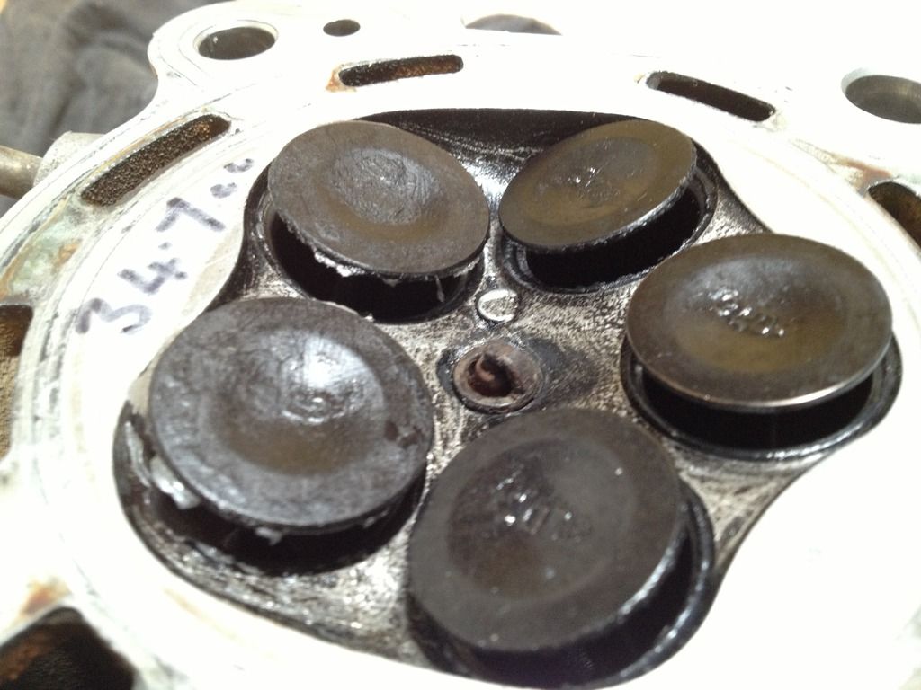
INLET VALVE TO EXHAUST VALVE CLEARENCE
Using the spare head fitted with std TRX valves at 4.5mm valve lift I have 1.5mm valve to valve clearance for overlap reference so will easily accomidate a 2mm overlap on exhaust and inlet valve even with 1mm oversize valves.
UPDATE...
This photo shows the valves is well over spec of the large duration cams I have ( 2.3mm in/ 3.4mm ex ) and photos of the realistic clearance with 1mm oversize valves is on the next page.

Last edited by cobbadiggabuddyblooo on Mon Feb 15, 2016 2:12 pm, edited 2 times in total.
laughter is the best medicine
-
cobbadiggabuddyblooo
- Site Sponsor
- Posts: 6809
- Joined: Thu Aug 28, 2008 9:19 am
- Location: Brisbane,Australia
Re: What did you do today? Cobba's rebuild
Penner cam shafts are have been ordered and will have a suprise for you all soon.
Their specs come in between the V2 and Megacycle but not symmetrical like the tornados or Kent D1580.
8.5mm lift .
Their specs come in between the V2 and Megacycle but not symmetrical like the tornados or Kent D1580.
8.5mm lift .
Last edited by cobbadiggabuddyblooo on Fri Jan 22, 2016 9:21 am, edited 3 times in total.
laughter is the best medicine
-
cobbadiggabuddyblooo
- Site Sponsor
- Posts: 6809
- Joined: Thu Aug 28, 2008 9:19 am
- Location: Brisbane,Australia
Re: What did you do today? Cobba's rebuild
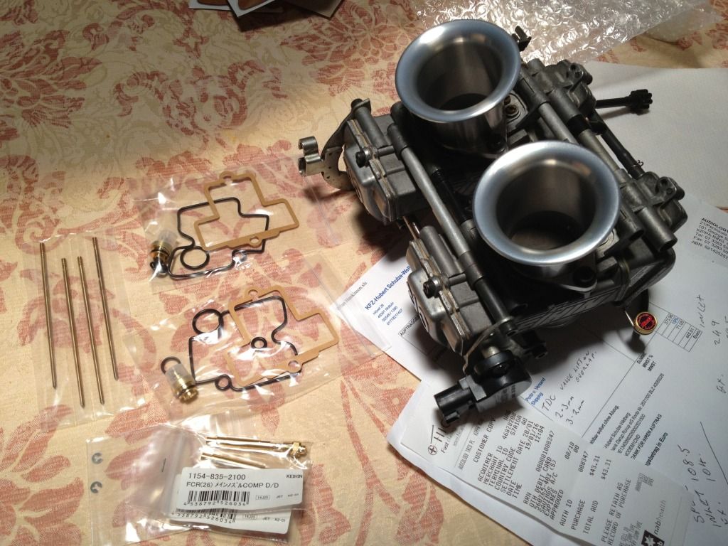
New bits n pieces arrived today to rebuild the carbies.
Much cheaper to get parts directly from Japan and about half the price on what I'd pay here from Show n Go in Adelaide.
I grabbed another spare needles and emushion tubes as they will wear again in time.
laughter is the best medicine
-
cobbadiggabuddyblooo
- Site Sponsor
- Posts: 6809
- Joined: Thu Aug 28, 2008 9:19 am
- Location: Brisbane,Australia
Re: What did you do today? Cobba's rebuild
Cams should arrive next week and look forward to finally getting back to tinkering on the motor instead of hrs of researching, gathering information and formatting something to compliment all the other components in the motor.
Basic fundamentals I've learnt on cam profiles, duration and lift which opened my mind to not stress about large numbers in duration.
Due to the oversize capacity and extra 4-5% from std duration is needed just to match the extra cc's.
Higher compression also allows for further duration without any issues.
Again having the ports flowed has allowed for a more aggressive ramp opening and the cams are asymmetrical opening faster and lifting a little earlier around 12 degrees difference from 0mm to 1mm compared to 2 degrees std. Again their is a faster ramp closing the the valve from full lift over the first couple of mm.
With 2.3mm intake lift at TDC and 3.2mm exhaust during overlap, the power cycle and exhaust cycle degrees would be different than if I was using a symmetrical cam with the same duration and lobe centre.
The std Trx cam profile, the Kent and Tornado all have symmetrical profiles.
To keep the intake charge velocity on the opening of the intake valve and amount of overlap, this is where the choice of bell mouth length comes into play.
I'll post some data info that I got on the cams shortly to show exactly what I mean by this.
In the mean time, here is a good link to give an explanation on what I'm putting into practice..
http://www.elgincams.com/campaper.html
Last edited by cobbadiggabuddyblooo on Fri Apr 01, 2016 12:02 pm, edited 4 times in total.
laughter is the best medicine
-
cobbadiggabuddyblooo
- Site Sponsor
- Posts: 6809
- Joined: Thu Aug 28, 2008 9:19 am
- Location: Brisbane,Australia
Re: What did you do today? Cobba's rebuild

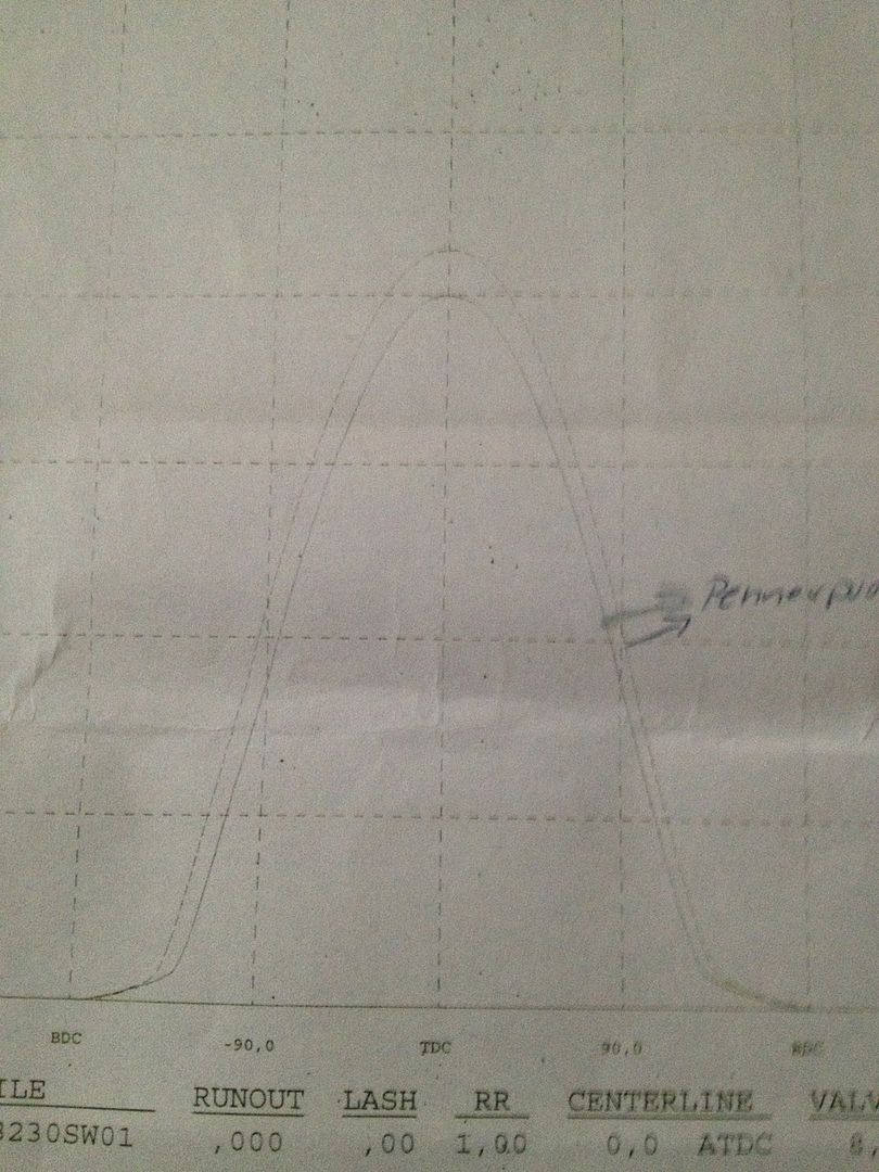
Here is the cam profile info for a std Trx cam and a I have all the profile info on the cams designated for my motor.
Below is a comparison of the std and Penner ground profile for my motor.
You can see the asymmetrical more agressive opening profile while retaining a softer closing of the valve under 1mm to fully closed .
Effectively this will skew the timing points and improve low end torque performance without sacrificing the total area under the curve.
Asymmetrical cam lobes..
In the past, both the opening and closing sides of a cam lobe were identical. More recently, designers developed asymmetric lobes, wherein the shape of the opening and closing sides differ. Asymmetry helps optimize the dynamics of a valvetrain system by producing a lobe with the shortest seat timing and the most area. The designer wants to open the valve as fast as possible without overcoming the spring's ability to absorb the valvetrain's kinetic energy, then close the valve as fast as possible without resulting in valve bounce. There are many different theories about how to design the most aggressive, stable profile.
Asymmetric lobes can better tailor the cam to specific cylinder head idiosyncrasies. To optimize airflow, some heads may need a slow opening intake, or a slower-closing exhaust.
Due to the differences in cylinder head, intake, and exhaust configuration, different engine combos are extremely sensitive to the camshaft's overlap region. Not only is the duration and area of the overlap triangle important but also its overall shape. Much recent progress in cam design has been due to careful tailoring of the shape of the overlap triangle. The most critical engine factors for optimizing overlap include intake system efficiency, exhaust system efficiency, and how well the heads flow from the intake toward the exhaust with both valves slightly open.
If all goes to plan I'm predicting another 10 RWHP to bring me to 115 RWBH and a nice flat torque curve at or above 100Nm from 4500 to 8500rpm
laughter is the best medicine
-
cobbadiggabuddyblooo
- Site Sponsor
- Posts: 6809
- Joined: Thu Aug 28, 2008 9:19 am
- Location: Brisbane,Australia
Re: What did you do today? Cobba's rebuild
http://www.classiczcars.com/uploads/mon ... 964708.jpg
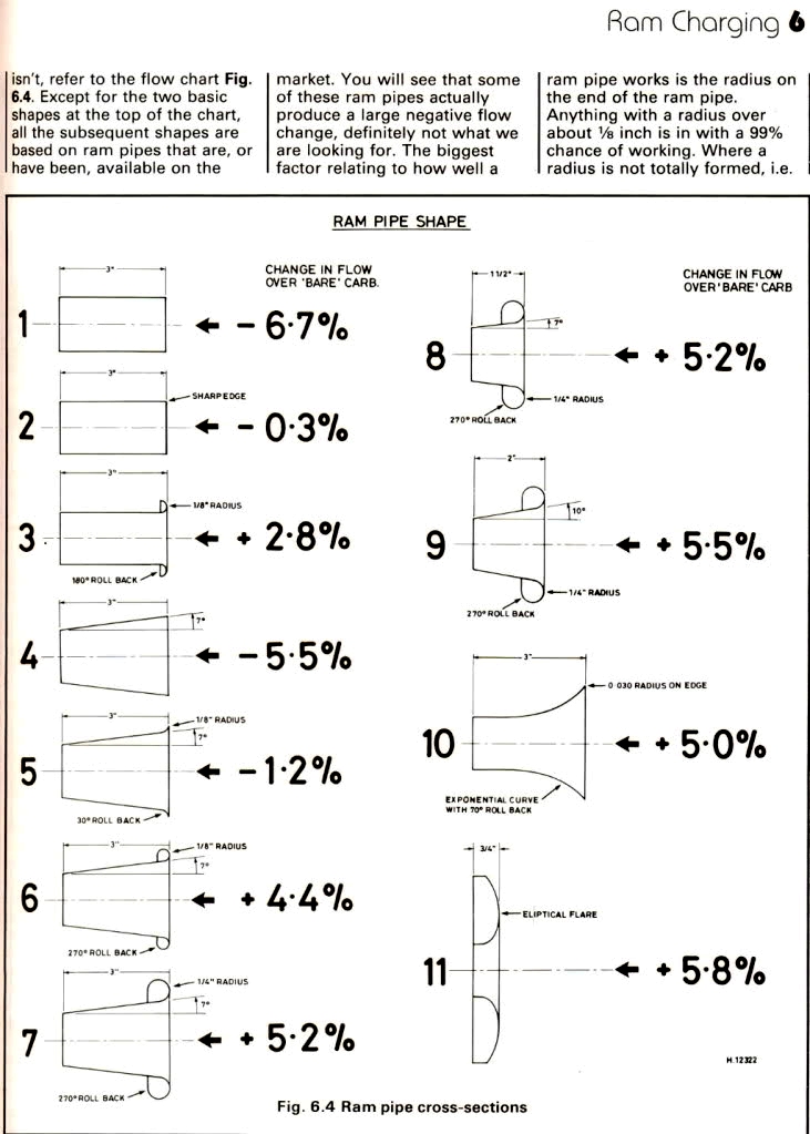
David Vizard
It's not only the tuned length for the intake pulse that can give you the desired gains but the overall shape and material used.
The new aluminium bellmouths fitted are an eliptical bellmouth with a 10% increase to the intake bell and around twice the % gains over the std plastic to a straight outlet .
All these little percentages add up .. It may only be 1.5hp at 4000 and 3 hp at 8000 with the 60mm length but you add that to the tuned length on the Akrapovic system and that's potentually now a 7hp at 4000 and 5.5hp gain at 7000rpm.
Density comes into play between plastic and alloy with resonance too.
http://www.academia.edu/10715724/Design ... uth_Intake
10% Eliptical by 1.7
Last edited by cobbadiggabuddyblooo on Mon Feb 01, 2016 2:37 pm, edited 4 times in total.
laughter is the best medicine
-
cobbadiggabuddyblooo
- Site Sponsor
- Posts: 6809
- Joined: Thu Aug 28, 2008 9:19 am
- Location: Brisbane,Australia
Re: What did you do today? Cobba's rebuild
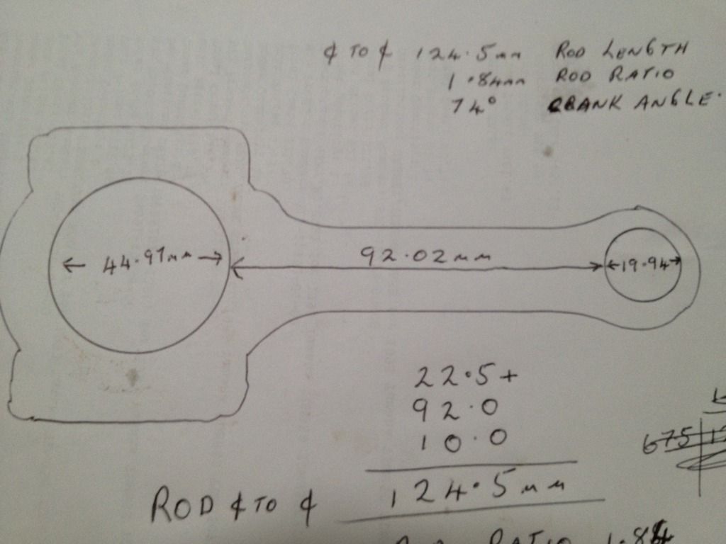
More notes as reference
Rod length ...124.5mm
Rod ratio...... 1.84
Crank angle ...74*
Reference link to remember
http://www.epi-eng.com/piston_engine_te ... basics.htm
http://www.elgincams.com/campaper.html
laughter is the best medicine
-
cobbadiggabuddyblooo
- Site Sponsor
- Posts: 6809
- Joined: Thu Aug 28, 2008 9:19 am
- Location: Brisbane,Australia
Re: What did you do today? Cobba's rebuild
Long Rod is faster at BDC range and slower at TDC range.
IV. DEFINITIONS
Short Rod -- Min Rod/Stroke Ratio -- 1.60 Max Rod/Stroke Ratio -- 1.80
Long Rod -- Min Rod/Stroke Ratio -- 1.81 Max Rod/Stroke Ratio -- 2.00
I. LONG ROD
A. Intake Stroke -- will draw harder on cyl head from 90-o ATDC to BDC.
B. Compression Stroke -- Piston travels from BDC to 90-o BTDC faster than short rod. Goes slower from 90-o BTDC to TDC--may change ign timing requirement versus short rod as piston spends more time at top. However; if flame travel were too fast, detonation could occur. Is it possible the long rod could have more cyl pressure at ie. 30-o ATDC but less crankpin force at 70-o ATDC. Does a long rod produce more efficient combustion at high RPM--measure CO, CO2? Find out!!
C. Power Stroke -- Piston is further down in bore for any given rod/crank pin angle and thus, at any crank angle from 20 to 75 ATDC less force is exerted on the crank pin than a shorter rod. However, the piston will be higher in the bore for any given crank angle from 90-o BTDC to 90-o ATDC and thus cylinder pressure could be higher. Long rod will spend less time from 90-o ATDC to BDC--allows less time for exhaust to escape on power stroke and will force more exhaust out from BDC to 90-o BTDC. Could have more pumping loss! Could be if exhaust port is poor, a long rod will help peak power.
D. Exhaust Stroke -- see above.
D. More exhaust lobe or a earlier exhaust opening may defeat a longer rod. I am saying that a shorter rod allows a earlier exhaust opening. A better exhaust port allows a earlier exhaust opening.
E. Definition of poor exhaust port. Becomes turbulent at lower velocity than a better port. Flow curve will flatten out at a lower lift than a good port. A good exhaust port will tolerate more exhaust lobe and the engine will like it. Presuming the engine has adequate throttle area (so as not to cause more than 1" Hg depression below inlet throttle at peak power); then the better the exhaust port is, the greater the differential between optimum intake lobe duration and exhaust lobe duration will be--ie. exh 10-o or more longer than intake Carbon buildup will be minimal if cyl is dry.
Effects of Long Rods
Pro:
» Provides longer piston dwell time at & near TDC, which maintains a longer state of compression by keeping the chamber volume small. This has obvious benefits: better combustion, higher cylinder pressure after the first few degrees of rotation past TDC, and higher temperatures within the combustion chamber. This type of rod will produce very good mid to upper RPM torque.
» The longer rod will reduce friction within the engine, due to the reduced angle which will place less stress at the thrust surface of the piston during combustion. These rods work well with numerically high gear ratios and lighter vehicles.
» For the same total deck height, a longer rod will use a shorter (and therefore lighter) piston, and generally have a safer maximum RPM.
Con:
» They do not promote good cylinder filling (volumetric efficiency) at low to moderate engine speeds due to reduced air flow velocity. After the first few degrees beyond TDC piston speed will increase in proportion to crank rotation, but will be biased by the connecting rod length. The piston will descend at a reduced rate and gain its maximum speed at a later point in the crankshaft’s rotation.
» Longer rods have greater interference with the cylinder bottom & water jacket area, pan rails, pan, and camshaft - some combinations of stroke length & rod choice are not practical.
To take advantage of the energy that occurs within the movement of a column of air, it is important to select manifold and port dimensions that will promote high velocity within both the intake and exhaust passages. Long runners and reduced inside diameter air passages work well with long rods.
Camshaft selection must be carefully considered. Long duration cams will reduce the cylinder pressure dramatically during the closing period of the intake cycle.
Effects of Short Rods
Pro:
» Provides very good intake and exhaust velocities at low to moderate engine speeds causing the engine to produce good low end torque, mostly due to the higher vacuum at the beginning of the intake cycle. The faster piston movement away from TDC of the intake stroke provides more displacement under the valve at every point of crank rotation, increasing vacuum. High intake velocities also create a more homogenous (uniform) air/fuel mixture within the combustion chamber. This will produce greater power output due to this effect.
» The increase in piston speed away from TDC on the power stroke causes the chamber volume to increase more rapidly than in a long-rod motor - this delays the point of maximum cylinder pressure for best effect with supercharger or turbo boost and/or nitrous oxide.
» Cam timing (especially intake valve closing) can be more radical than in a long-rod motor.
Con:
» Causes an increase in piston speed away from TDC which, at very high RPM, will out-run the flame front, causing a decrease in total cylinder pressure (Brake Mean Effective Pressure) at the end of the combustion cycle.
» Due to the reduced dwell time of the piston at TDC the piston will descend at a faster rate with a reduction in cylinder pressure and temperature as compared to a long-rod motor. This will reduce total combustion.
Rod Ratio vs. Intake Efficiency
An “n†value of 1.75 is considered “ideal†by some respected engine builders, if the breathing is optimized for the design.
laughter is the best medicine