What did you do today? Cobba's rebuild
Moderators: trixynut, Mincehead, dicky, phuk72, Jak, Kevtrx849
-
cobbadiggabuddyblooo
- Site Sponsor
- Posts: 6809
- Joined: Thu Aug 28, 2008 9:19 am
- Location: Brisbane,Australia
Re: What did you do today? Cobba's rebuild
$82 posted (if in oz) which is about $10 cheaper than a std OEM gasket.
Last edited by cobbadiggabuddyblooo on Fri Nov 28, 2014 2:13 pm, edited 1 time in total.
laughter is the best medicine
-
cobbadiggabuddyblooo
- Site Sponsor
- Posts: 6809
- Joined: Thu Aug 28, 2008 9:19 am
- Location: Brisbane,Australia
Re: What did you do today? Cobba's rebuild
Brian
John here I have your measurement's for you .
stroke 67-5mm
Head volume 33-8 cc
piston deck 1-25 mm
Oem head gasket 1mm
90-5 mm bore
Worked out to
11.54 : 1 compression at 1.25mm/0.050" deck height.
From these figures I have used the comp ratio calculator to achieve the piston dome volume of 8.7cc
But the deck height now has decreased to 1.15mm / 0.046" due to the 0.1mm thinner copper head gasket I am using
. Advice from John Coonan 0.046" / 0.9mm minimum safe deck height
(0.48 was the figure given on the JE 878 pistons from TTS)


NOTE ADDED
Head gasket needs to be worked out as compressed thickness so approx 0.75-0.8 thickness not 1mm
THIS GIVES A DOME VOLUME OF 5.3cc
which is 0.4cc larger than the Arias with a similar piston crown profile and same compression ratio.
not 8.7cc as stated above.
John here I have your measurement's for you .
stroke 67-5mm
Head volume 33-8 cc
piston deck 1-25 mm
Oem head gasket 1mm
90-5 mm bore
Worked out to
11.54 : 1 compression at 1.25mm/0.050" deck height.
From these figures I have used the comp ratio calculator to achieve the piston dome volume of 8.7cc
But the deck height now has decreased to 1.15mm / 0.046" due to the 0.1mm thinner copper head gasket I am using
. Advice from John Coonan 0.046" / 0.9mm minimum safe deck height
(0.48 was the figure given on the JE 878 pistons from TTS)
NOTE ADDED
Head gasket needs to be worked out as compressed thickness so approx 0.75-0.8 thickness not 1mm
THIS GIVES A DOME VOLUME OF 5.3cc
which is 0.4cc larger than the Arias with a similar piston crown profile and same compression ratio.
not 8.7cc as stated above.
Last edited by cobbadiggabuddyblooo on Wed Dec 10, 2014 6:27 am, edited 4 times in total.
laughter is the best medicine
-
cobbadiggabuddyblooo
- Site Sponsor
- Posts: 6809
- Joined: Thu Aug 28, 2008 9:19 am
- Location: Brisbane,Australia
Re: What did you do today? Cobba's rebuild
11.71 ;1 compression ratio with 0.1 mm thinner copper head gasket..
Piston dome volume 5.3cc
if I decrease the thickness of my head gasket by 0.1mm this too will decrease my deck height by 0.1mm
correct????
11.88 : 1 compression ratio is the figure I get with a 0.9mm gasket and 1.15 mm revised deck height.(not 1.25mm)
Can someone confirm if I have this final calculation correct ..
Piston dome volume 5.3cc
correct????
11.88 : 1 compression ratio is the figure I get with a 0.9mm gasket and 1.15 mm revised deck height.(not 1.25mm)
Can someone confirm if I have this final calculation correct ..
Last edited by cobbadiggabuddyblooo on Wed Jan 07, 2015 8:10 am, edited 1 time in total.
laughter is the best medicine
-
Rod.s

- Site Sponsor
- Posts: 1406
- Joined: Sun Apr 25, 2010 11:01 am
- Location: Brisbane, Australia
Re: What did you do today? Cobba's rebuild
Just to clarify, the deck height is not the same as the piston deck.cobbadiggabuddyblooo wrote:11.71 ;1 compression ratio with 0.1 mm thinner copper head gasket..
Piston dome volume 8.7cc
correct????
11.88 : 1 compression ratio is the figure I get with a 0.9mm gasket and 1.15 mm revised deck height.(not 1.25mm)
Can someone confirm if I have this final calculation correct ..
The deck height is the distance from the piston pin to the "deck" of the piston. The deck clearance is the distance from the deck of the piston to the contact point of the cylinder head.
John gave you the piston deck as 1.25mm which is the "deck clearance" if you use a thiner gasket (0.9mm) then the piston deck clearance will decrease to 1.15mm and your compression ratio will increase. So what you have calculated is correct but you've mixed up the terms
If it's not made in China, it's a fake!
-
brockzila

- TRX-Enthusiast
- Posts: 348
- Joined: Mon Feb 18, 2008 2:30 pm
Re: What did you do today? Cobba's rebuild
have a look at this
it explains in a simple diagram what the different terms and ways to measure them.
http://www.matrixgarage.com/content/4ag ... ormation-0
it explains in a simple diagram what the different terms and ways to measure them.
http://www.matrixgarage.com/content/4ag ... ormation-0
Is it Brock friendly???
-
cobbadiggabuddyblooo
- Site Sponsor
- Posts: 6809
- Joined: Thu Aug 28, 2008 9:19 am
- Location: Brisbane,Australia
Re: What did you do today? Cobba's rebuild
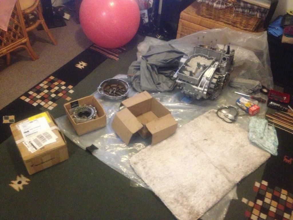
Measured the stack height and it came in at 1.2mmcobbadiggabuddyblooo wrote:
NOTE..
The 6 holes on the outer edge by the springs of the top plate is where you take your stack height measurements from.
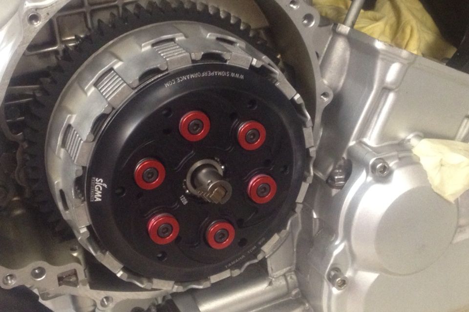
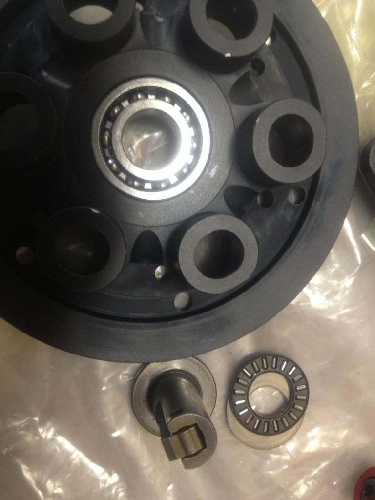
But what needed to be done was I needed to remove the bearing and washer the clutch pull rod ran on .
The std yamaha pressure plate is just a hole and the bearing/plate was needed on the rod with the rotating clutch.
The Sigma slipper clutch has a bearing fitted into the pressure plate itself so this bearing and washer is obsolete plus with these items in place, you don't have the clearance and the rod will sit against the centre shaft.
laughter is the best medicine
-
cobbadiggabuddyblooo
- Site Sponsor
- Posts: 6809
- Joined: Thu Aug 28, 2008 9:19 am
- Location: Brisbane,Australia
Re: What did you do today? Cobba's rebuild
Great link and explains in detail more so exactly what I'm looking for.brockzila wrote:have a look at this
it explains in a simple diagram what the different terms and ways to measure them.
http://www.matrixgarage.com/content/4ag ... ormation-0
And I can see the terminology mistake
I feel like such a deck height
It also explains the reasoning why the difference in compression height on the JE 878 and arias 878 i have...
Arias 878 has an increased comp height from 26.5 on the std OEM piston to 26.8 mm .
This obviously allows them to lift compression to 12:1 and still keep a flat top and why the JE 878 piston uses the std OEM comp height but a domed piston to achieve the same as std 10.5:1 compression but with deeper valve reliefs.
The Ross pistons that I have on this rebuild , John has given me a deck clearance of 1.5mm after taking a little off the barrels.
Arias have gone from these values so if I use those this will get my deck clearance a little lower at 1.2mm..
So its not rocket science...
Thanks
This only confirms what is stated on the link. The only way to get it right is to do the maths what ever piston you use. Plus you don't know if the barrels have been decked ( like what John has done on my barrels) or if the head has been shaved in any way.
Last edited by cobbadiggabuddyblooo on Sun Mar 13, 2016 1:28 pm, edited 1 time in total.
laughter is the best medicine
-
Rod.s
- Site Sponsor
- Posts: 1406
- Joined: Sun Apr 25, 2010 11:01 am
- Location: Brisbane, Australia
Re: What did you do today? Cobba's rebuild
Anyone got a good piston ring compressor……..Brian needs one 
If it's not made in China, it's a fake!
-
cobbadiggabuddyblooo
- Site Sponsor
- Posts: 6809
- Joined: Thu Aug 28, 2008 9:19 am
- Location: Brisbane,Australia
Re: What did you do today? Cobba's rebuild
Productive days after having been chased by the storm that came through yesterday.
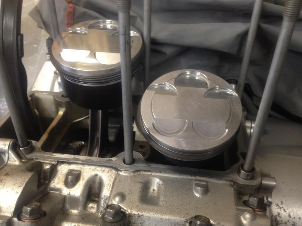
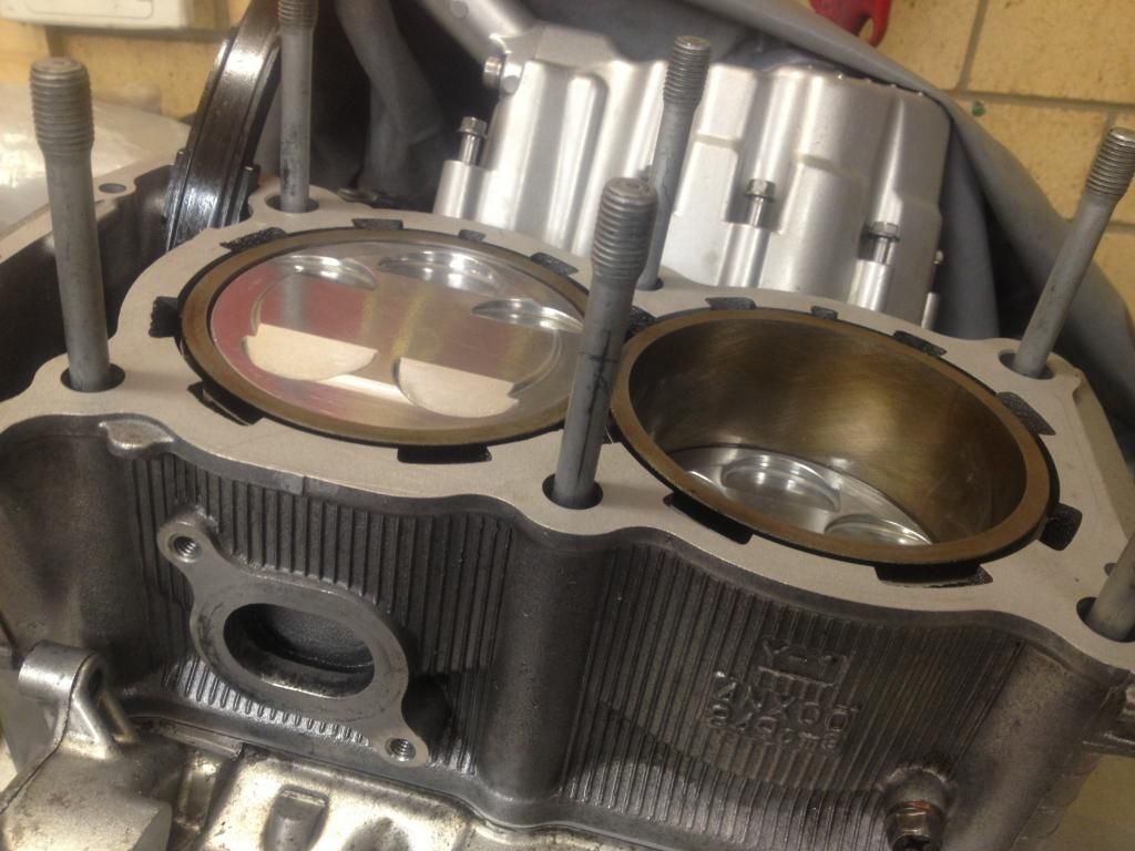
Time to set up the pistons and barrels for install.
Ring gaps is set and the pistons use the std Yamaha 1mm oversize rings so as per the manual, make sure the T mark faces the upper side of the top compression ring.
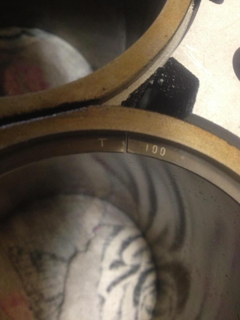
Rings in place and the gaps have been staggered around the piston and the inside pair of lock wires have been located into the pistons.
I found it easier when fitting the oil rings to place the expander spacer in the ring land first then place the upper and lower oil scraper rings.
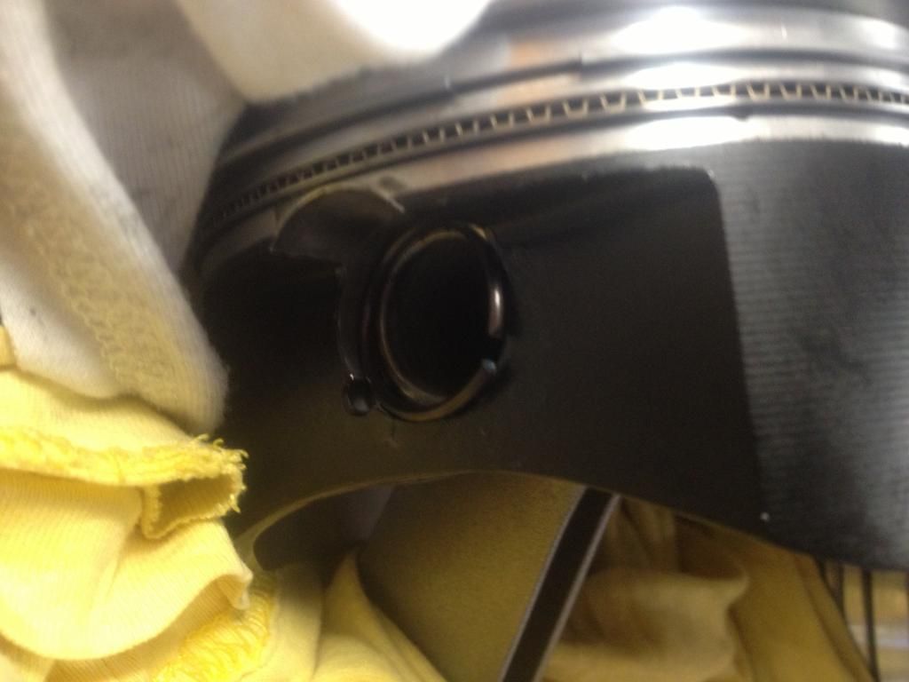
Place the pistons onto the rod (don't forget the lube) and slide your wrist pins through the piston and up against the lock wire already installed on the inner side of the piston.
Lock wires can be a little tricky but I managed by squeezing the clip together while placing the opposing side into the seat for the lock wire. Then just push both ends with to locate it into the groove..
New o rings placed around the base of the barrels and make sure you feed the timing chain guide into the cavity and cam chain..OK where is the camchain??
Off with the oil pumps again and chain in place and fed up through the barrels.. A little reminder as this is one thing not mentioned in the manual at the install oil pump stage so just something to remember if you follow the manual..
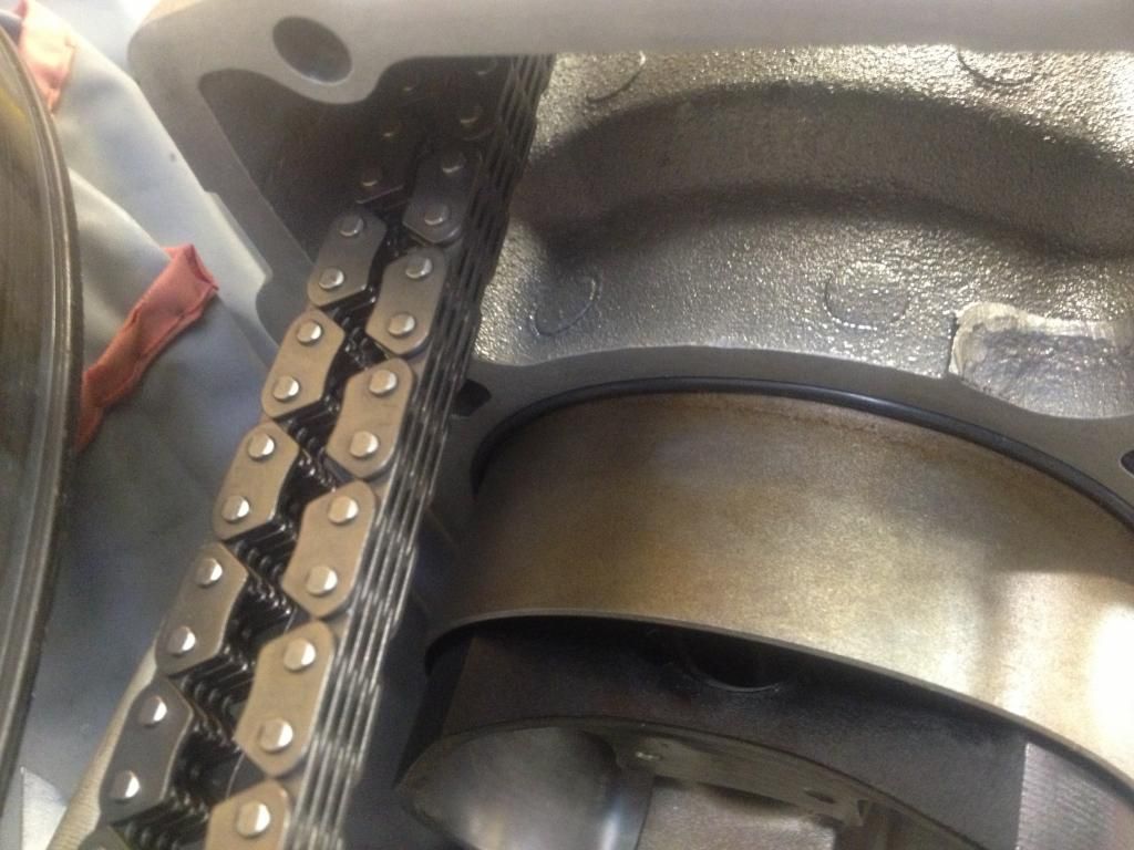
OK time for a coffee and grab the base gasket and dowels, camchain fed through the cavity and as per the manual, feed the pistons into the bores while holding the barrels in the other hand.. A little giggling whallah...
off again as I put the camchain through but forgot the guide this time...
All right once again and next problem I came across..
Don;t tie the cam chain and guide to the intake side of the barrels as the guide will locate itself into the cam chain adjuster hole as you lower the barrels..
OK... Cam chain...check .... Guide... check ... both Wired in place towards the front of the motor..
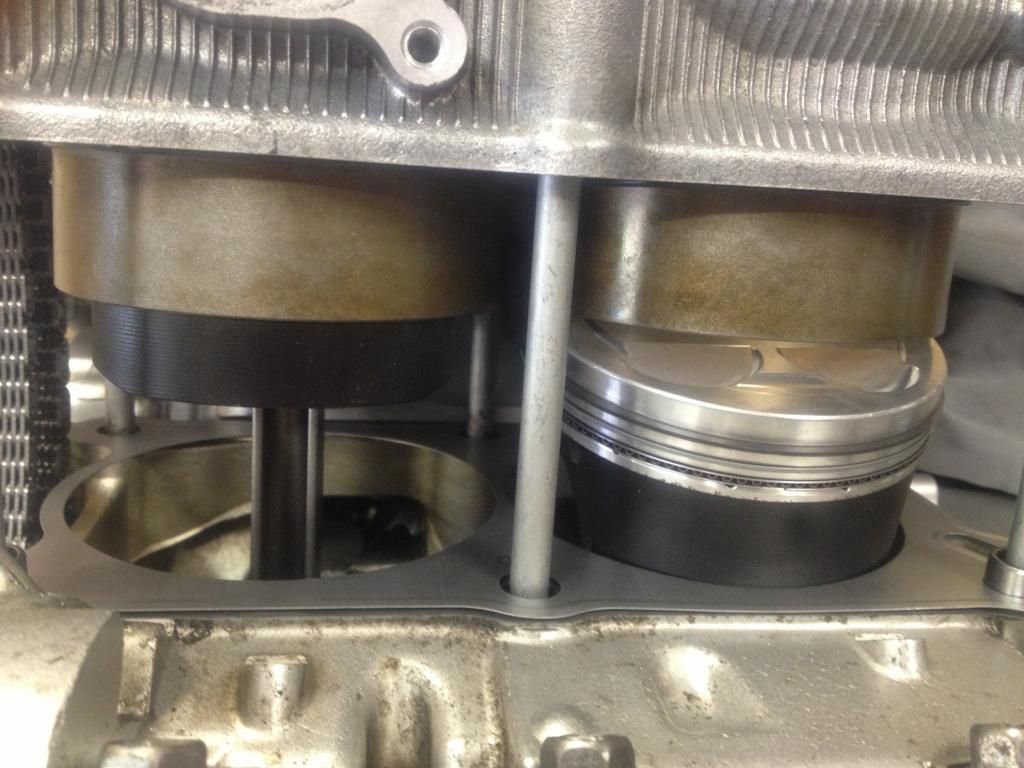
Check... I found it easier to do as the manual and use 1 hand to feed the piston and rings into the bore while holding the barrels with the other hand.
The pistons will tend to rock a little vertically forward and back in the bore as you feed it over the rings and it's easier to manage all this as well as the side to side horizontal movement.
Suggestions of chocking the opposing piston I tried but as I said, I found it easier to do this all by yourself as per the manual.
Time to set up the pistons and barrels for install.
Ring gaps is set and the pistons use the std Yamaha 1mm oversize rings so as per the manual, make sure the T mark faces the upper side of the top compression ring.
Rings in place and the gaps have been staggered around the piston and the inside pair of lock wires have been located into the pistons.
I found it easier when fitting the oil rings to place the expander spacer in the ring land first then place the upper and lower oil scraper rings.
Place the pistons onto the rod (don't forget the lube) and slide your wrist pins through the piston and up against the lock wire already installed on the inner side of the piston.
Lock wires can be a little tricky but I managed by squeezing the clip together while placing the opposing side into the seat for the lock wire. Then just push both ends with to locate it into the groove..
New o rings placed around the base of the barrels and make sure you feed the timing chain guide into the cavity and cam chain..OK where is the camchain??
Off with the oil pumps again and chain in place and fed up through the barrels.. A little reminder as this is one thing not mentioned in the manual at the install oil pump stage so just something to remember if you follow the manual..
OK time for a coffee and grab the base gasket and dowels, camchain fed through the cavity and as per the manual, feed the pistons into the bores while holding the barrels in the other hand.. A little giggling whallah...
All right once again and next problem I came across..
Don;t tie the cam chain and guide to the intake side of the barrels as the guide will locate itself into the cam chain adjuster hole as you lower the barrels..
OK... Cam chain...check .... Guide... check ... both Wired in place towards the front of the motor..
Check... I found it easier to do as the manual and use 1 hand to feed the piston and rings into the bore while holding the barrels with the other hand.
The pistons will tend to rock a little vertically forward and back in the bore as you feed it over the rings and it's easier to manage all this as well as the side to side horizontal movement.
Suggestions of chocking the opposing piston I tried but as I said, I found it easier to do this all by yourself as per the manual.
Last edited by cobbadiggabuddyblooo on Fri Dec 05, 2014 9:04 am, edited 1 time in total.
laughter is the best medicine
-
cobbadiggabuddyblooo
- Site Sponsor
- Posts: 6809
- Joined: Thu Aug 28, 2008 9:19 am
- Location: Brisbane,Australia
Re: What did you do today? Cobba's rebuild
Finally.. now I'm happy...
First copper head gasket was a not quite right.. A std head gasket was used a s a template but he didn't realise there where locating dowels and he used a nother point as his reference point.
So to get it spot on, I gave him the spare head and barrels I have to size up the gasket and to get the cad program spot on and he's making up a new gasket ..
So now next week will be to calibrate the timing wheel to TDC.
Before putting the head on and dialing in the cams, I'll bolt solid bar across the piston, rotate the motor and when it stops against the bar I'll note the degrees on the timing wheel. Then I'll rotate the motor back the other way till again is stops against the bar and note the degrees.
I can then count how many degrees between each of these measurements (eg 10+BTDC and 12* ATDC = 22*) I'll half this measurement and this will place TDC at 1* ATDC.
So I place the crank at 1*ATDC and I move the pointer I will use to 0* on the wheel so all is calibrated and a far more accurate than using the factory timing mark..
This shall be fun... and I'm sure I'll learn from my mistakes once again and pass on any tips...
laughter is the best medicine
-
cobbadiggabuddyblooo
- Site Sponsor
- Posts: 6809
- Joined: Thu Aug 28, 2008 9:19 am
- Location: Brisbane,Australia
Re: What did you do today? Cobba's rebuild
Yes .. I need one to compress that ring between your arse cheeks... WPHS and your farts mate.. No penalty rate will have me working around you when you let one fly...Rod.s wrote:Anyone got a good piston ring compressor……..Brian needs one
laughter is the best medicine
-
cobbadiggabuddyblooo
- Site Sponsor
- Posts: 6809
- Joined: Thu Aug 28, 2008 9:19 am
- Location: Brisbane,Australia
Re: What did you do today? Cobba's rebuild
Balance factor notes ...
OEM piston rings pin = 406g
JE878 piston ring pin = 448g
Arias 878 piston rings pin = 380g
Ross with OEM trx pin = 423g
Ross original 432g
Balance factors on std crank- OEM rods, pistons (50%)
1::: JE 878 + OEM rods 46%
2::: JE 878 + Carrillo rods. 55%
3::: Arias 878 + OEM rods. 55%
4::: Arias 878 + Carrillo rods 62%
1. Remove weight from piston / pin to achieve 50%
2 , 3 & 4 remove weight from bob weights on crank to achieve 50% balance factor on the crank.
Balancing the crank you will also find they will balance the pistons, rods pins within a couple of points( 0.?grams) of each other . The same level of accuracy will apply on the crank bob weights.
1or 2% either side of 50% was the acceptable figure for a street/ trackday motorcycle Grant quoted to me from Brisbane Engine Balancing when enquiring about balance factors and using different weight pistons.
Last edited by cobbadiggabuddyblooo on Fri Dec 11, 2015 1:07 pm, edited 1 time in total.
laughter is the best medicine
-
cobbadiggabuddyblooo
- Site Sponsor
- Posts: 6809
- Joined: Thu Aug 28, 2008 9:19 am
- Location: Brisbane,Australia
Re: What did you do today? Cobba's rebuild
With Rod having plans for xmas and after i removed the motor and big thanks to Rod for the time , effort and help and allowing me to utilise his garage and tools .
So where else can it go,???
It's so good having a very understanding partner...
But now I'm removing the crank once again for further balancing to the Arias pistons..
So where else can it go,???
It's so good having a very understanding partner...
But now I'm removing the crank once again for further balancing to the Arias pistons..
laughter is the best medicine
-
cobbadiggabuddyblooo
- Site Sponsor
- Posts: 6809
- Joined: Thu Aug 28, 2008 9:19 am
- Location: Brisbane,Australia
Re: What did you do today? Cobba's rebuild
Barrels are back off and I'm wondering if I can leave the clutch on the shaft as I should only have to remove the alt. rotor to access the balance shafts before splitting the cases once again.
Good link on how to remove the alternator rotor.. Thanks kev
http://www.trx850.com/phpBB_forum/viewt ... =36&t=7051
Good link on how to remove the alternator rotor.. Thanks kev
http://www.trx850.com/phpBB_forum/viewt ... =36&t=7051
laughter is the best medicine
-
dandywarhol
- Site Sponsor
- Posts: 1639
- Joined: Fri Nov 24, 2006 12:56 pm
- Location: Edinburgh, Scotland
Re: What did you do today? Cobba's rebuild
I was always under the impression that the crank webs were the equivalent of the piston and 33% of the rod weight for dynamic balance.................. 
1996 TRX 850, blue, Ohlins 46HRCLS, Race Tech Gold Valves, 0.90 springs, Venom pipes, R6 brakes............
1974 Yamaha RD250A, Candy Blue
1998 Yamaha SZR660, blue of course
1967 Yamaha TD1C 250, Blue and white
1974 Yamaha RD250A, Candy Blue
1998 Yamaha SZR660, blue of course
1967 Yamaha TD1C 250, Blue and white