IGNITION SWITCH WIRING PATTERN

Moderators: trixynut, Mincehead, dicky, phuk72, Jak, Kevtrx849

Post Reply
cobbadiggabuddyblooo
Site Sponsor
Posts: 6809
Joined: Thu Aug 28, 2008 9:19 am
Location: Brisbane,Australia

IGNITION SWITCH WIRING PATTERN

Post by cobbadiggabuddyblooo » Sat Jun 14, 2014 11:41 am

I had to replace the ignition switch on my TRX but in wiring in an aftermarket 2position switch I have a dead short .

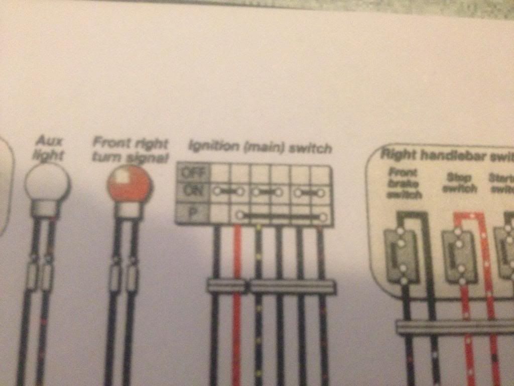
The Trx has a 4 wire ignition so my suspicions are the red being power into the switch connects to the brown/blue with the key on. This powers all the systems ( lighting,signal,start and cooling)
I have looked at the wiring diagrams and I feel the other two wires being blue/yellow and blue/black don't actually draw power from the turning of the switch but just link together so this allows your side stand and neutral switches to connect to the ECU .

Can someone confirm my suspicions at all ??
When you look in the Yamaha workshop manual at the 4 different wiring diagrams with highlighting the systems (lighting, cooling, signal & starting) on the wiring diagrams, they all seem to draw there power from brown/blue from the ignition switch.
Image
Image
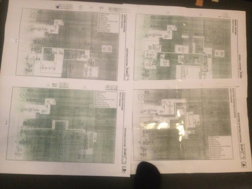
But the Haynes manual diagram like i posted up yesterday looks like it shows power being delivered across all ????
I have done this and developed a dead short as when I turn the key on I can see voltage dropping at an alarming rate in seconds from the battery and I'm thinking this is because its earthing through the side stand/neutral switches. These functions ultimately should be dealt with with voltage supplied from the ECU. and not directly powered..
Anyone know if I'm barking up the wrong tree on this????
laughter is the best medicine

User avatar
Tarwetijger
TRX-Enthusiast
Posts: 1537
Joined: Tue May 15, 2007 9:31 am
Location: Netherlands, Assen
Contact:

Re: IGNITION SWITCH WIRING PATTERN

Post by Tarwetijger » Sun Jun 15, 2014 8:15 am

Look at the dots in row "ON", is connects three pairs of wire with each other.
"P" is for parking light, it just connects red (which is main power indeed) to brown/black (i suppose, can't see very properly) - it doesn't connect the wires in between, although it might look like as it does.

cobbadiggabuddyblooo
Site Sponsor
Posts: 6809
Joined: Thu Aug 28, 2008 9:19 am
Location: Brisbane,Australia

Re: IGNITION SWITCH WIRING PATTERN

Post by cobbadiggabuddyblooo » Sun Jun 15, 2014 8:57 am

Yes realised the difference this morning Robert .. Cheers and now I know what the p actually stands for.. :lol: :lol:
Park lights are not std on the Aussie models nor the 6 wire ignition like the Haynes wiring diagram shows.
laughter is the best medicine

KESSU
TRX-Enthusiast
Posts: 7
Joined: Thu Jun 12, 2014 11:36 am
Location: Central Coast, NSW Australia

Re: IGNITION SWITCH WIRING PATTERN

Post by KESSU » Thu Jul 31, 2014 12:40 am

Hi Cobbadigga...
Just posted on Aus site about the wiring diagram,
how to replace the ignition with switch.

Do you have the Aus wiring?

Cheers

cobbadiggabuddyblooo
Site Sponsor
Posts: 6809
Joined: Thu Aug 28, 2008 9:19 am
Location: Brisbane,Australia

Re: IGNITION SWITCH WIRING PATTERN

Post by cobbadiggabuddyblooo » Thu Jul 31, 2014 3:49 am

Ignition barrell...
Red and Brown/ blue which are the two thickest wires and these are your main power feeds in and out.

Red ( R ) -power entering IN to the ignition barrell and the Brown/Blue ( Br/L ) wire is power OUT which travells to you main fuses ..

The other 2 thinner wires are,
Blue/Yellow ( L/Y ) is the side stand and clutch cut out switches entering IN to the ignition barrell and the Blue/Black ( L/B) heads OUT to the ECU.

When your ignition barrell is turned OFF........this disconnects main power to your fuses.
...BUT, as I found out. #-o ,
It connects the another curcuit ... cut out switches to the ecu (L/Y to L/B)
So if anyone tries to hotwire your bike by bypassing the ignition power from the barrell, this won't allow spark because this extra cut out link to the ECU effectively grounds it, so no spark.

When you turn your ignition barrell ON...... this gives power and spark because this dis-connects the extra ECU/cut out switches link when the ignition is OFF.

The Side stand, clutch and neutral switches all work in conjuction with the kill switch on the handlebars too,
so this allows it to funtion in earthing off the ECU when nessesary with the ignition barrell in both the OFF or ON position .

So make sure if you use an after market 4 pole switch this is the way the switch is set up..
Otherwise use a 2 pole switch (power in/out) and DON'T connect the 2 thinner cables (cut out/ECU) and insulate the connectors.
The side stand, neutral, clutch switch also work in conjuntion with the kill switch so these functions will work as per normal with the two wires just insulated.
These 2 wires are just an extra loop in the curcuit that won't give you that added security through the ignition barrel.

Wiring diagram codings
POWER
R... red
Br/L... Brown/Blue

SWITCH/ECU
L/Y... Blue/Yellow
L/B... Blue/Black


As for wiring diagram..
I have the workshop manual downloaded into my computer and what I did to make it easier to read was print the diagrams off but Janet changed the sizing and format on the print window on the computer. 8)
So 1 page from the manual was printed out in a block using 4 pages.
I just stuck them all together and you can see the reflection of some wide sticky tape on the 4 big print outs on the previos post...
Now I have the 4 wiring diagrams for the curcuits on sheets 600mm x 400mm and they are so much easier to read and follow the lines as you can see above.
laughter is the best medicine

KESSU
TRX-Enthusiast
Posts: 7
Joined: Thu Jun 12, 2014 11:36 am
Location: Central Coast, NSW Australia

Re: IGNITION SWITCH WIRING PATTERN

Post by KESSU » Thu Jul 31, 2014 6:02 am

Thanx Cobbadigga...
I should manage to connect the switch now.
May have a look at some aftermarket remote or other simple ignition mechanism,
so I won't need to worry if leaving the bike in Bondi etc. ;)

KESSU
TRX-Enthusiast
Posts: 7
Joined: Thu Jun 12, 2014 11:36 am
Location: Central Coast, NSW Australia

Re: IGNITION SWITCH WIRING PATTERN

Post by KESSU » Thu Jul 31, 2014 9:00 am

Got a 3PDT (3-pole) togle switch, http://m.jaycar.com.au/m_productView.asp?ID=ST0505
It should do the job if I understood the wiring correct...!?
It's rated for 3Amp. Is that enough?

KESSU
TRX-Enthusiast
Posts: 7
Joined: Thu Jun 12, 2014 11:36 am
Location: Central Coast, NSW Australia

Re: IGNITION SWITCH WIRING PATTERN

Post by KESSU » Fri Aug 08, 2014 11:06 pm

I used a 2-pole switch to replace the egnition barrel.
The thinner wires need to be connected.

Post Reply